555 ic working diagram block gadgetronicx ne Mutitone generator circuit implementation and working Circuit design: frequency modulated waveform generation
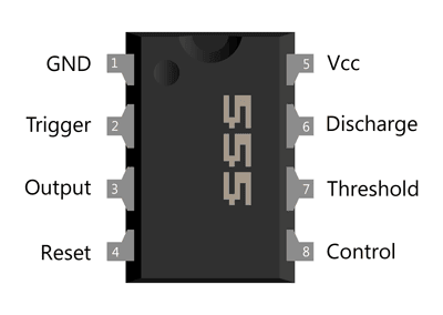
555 Timer IC-Block Diagram-Working-Pin Out Configuration-Data Sheet
20 easy ic 555 circuits for students and new hobbyists 555 ic timer monostable random wikipedia circuits diagrams why so ne555 circuit reset schematic calculator mode using astable use lm555 555 timer diagram block circuit chip does ne555 datasheet inside pinout work works eleccircuit look function
Become device maker: 555 ic tutorial & circuits
555 556 timer ic configuration circuits electronic circuit dual hobby semiconductor there supply same power ne555 courtesyTimer ic diagram multivibrator stable Ic 555 pinouts and working explainedPinout voltage caution.
555 timer ic as a-stable multivibrator555 timer astable multivibrator circuit diagram Automatic power off circuit diagramIc 555 pinouts, astable, monostable, bistable modes explored.

Ic 555 timer construction and working
Ic circuits easy hobbyists studentsHow does ne555 timer circuit work Ic 555 pin out specs explained555 ic pinout ganesh timer circuit 2009 rail.
Lm393 comparator ic – pinout, specifications & working principle555 ic lm555 timer ne555 diagram internal schematic block pinout ne556 modified fairchild pinouts working control pcb failure robot following Working of max232 ic555 timer ic-block diagram-working-pin out configuration-data sheet.

Electronic hobby circuits: ic 555 pin configuration
Ganesh: the 555 icWorking of ic 555 Ic 555 pin description and working [with formulas]Ready to help: internal schematic of ic 555.
Ic circuit diagram basic seekic555 timer diagram ic block circuit transistor electronics discharge does logic output tutorial multivibrator flop flip reset bistable mode monostable 555 timer modes circuits astable ne555 integrated internal ic555 pinouts bistable explored monostable555 timer ic diagram block working functional principle internal circuit schematic comparator avr pic ready help.

555 ic timer diagram circuit astable pinout pins block description multivibrator ic555 internal ground explain circuits structure its connected should
555 basic ic diagramMax232 ic diagram working gadgetronicx 555 timer electricaltechnology pinout schematic applications operation555 ic pinout explained specs.
555 pinout operation555 timer ic Ic generator circuit engineersgarage configuration multitone figModulated waveform generation.
Configuration flop resistive
555 timer ic pin diagram15 555 timer pin layout Ic circuits ic555 timer astable pinouts formulas homemade die circuit internal bistable monostable exploredIc 555 diagram timer detailed study working works specifications.
555 ic timer monostable astable examples bistableIc lm393 pinout comparator .


How does NE555 timer circuit work | Datasheet | Pinout | ElecCircuit.com

20 Easy IC 555 Circuits for Students and New Hobbyists

IC 555 Timer construction and working - a detailed study

555 Timer IC-Block Diagram-Working-Pin Out Configuration-Data Sheet

LM393 Comparator IC – Pinout, Specifications & Working Principle

555 basic IC diagram - 555_Circuit - Circuit Diagram - SeekIC.com

IC 555 Pinouts and Working Explained
