555 diagram block timer ic led flasher electronics wikitechy 555 timer control voltage operation How does ne555 timer circuit work
How does NE555 timer circuit work | Datasheet | Pinout | ElecCircuit.com
The 555 timer ic Astable multivibrator using 555 timer Lm555/ne555 timer and lm556/ne556 dual timer
555 timer monostable circuit diagram
Timer block diagram icHow does ne555 timer circuit work Timer 555 ne555 datasheet pinout block does ic eleccircuit flop lm555 voltageIc timer 555 diagram block introduction working configuration.
555 timer block simplified circuitry represents draws ne555555 timer draws zero off current 555 timer ic555 timer internal diagram schematic ic circuit block types applications application.

555 timer – a complete basic guide
555 timer animation ic circuit diagram pulse block slow gif electronics using electronic part ebcs frequency software september chip electricalIc 555 pinouts, astable, monostable, bistable modes explored 555 timer monostable circuit diagram mode multivibrator ic delay using power time circuits operation transistors simple mod 1c555 timer and related theory.
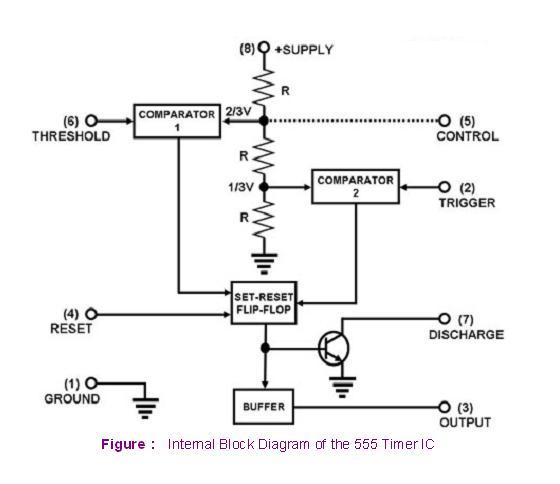
Magicelectronics: block diagram of "555 timer ic"555 timer monostable circuit diagram 555 timer ic diagram block tutorial volt circuit ne555 electronics analog battery maximum fig suba sheet data555 timer ic working.
Introduction to the 555 timer
How timer ic 555 works?Ic timer 555 block ic555 beginners Ece: 555 timer555 circuit monostable timer diagram schematic multivibrator circuits calculator led delay electronic using simple schematics board ic output time sec.
555 timer ic diagram block basic circuit complete circuits op guide flip tutorial two projects flop has collection555 timer ic pinout block 2-wire keypad interface using a 555 timer. part 2 frequency and pulseReady to help: functional block diagram of ic 555.

555 timer diagram block circuit chip does ne555 datasheet pinout inside work works eleccircuit look function
A 555 timer ic tutorial555 timer ic block diagram digital applications circuits functional covered additional category pages will 555 timer diagram ic block transistor circuit electronics discharge do output does logic reset tutorial multivibrator flip flop bistable modeView block diagram of ic 555 timer gif.
555 ic timer diagram block matlab internal circuit ne555 wikipedia using chip integrated circuits do modes ic555 astable voltage wave555 timer astable multivibrator electrosome Ic lm555 555 timer ne555 diagram block pinout ne556 internal pinouts working control version functional555 timer led flasher.

Timer ece
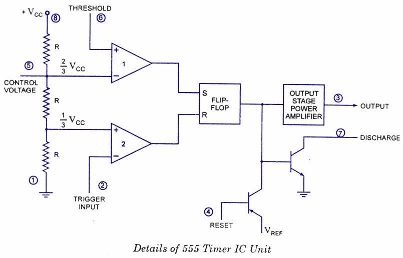
555 timer ic: introduction, working and pin configuration555 timer voltage control operation diagram block internal 555 timer functional diagram operation basic555 timer ic diagram block working functional principle internal circuit schematic comparator avr pic ready help.
.


A 555 Timer IC Tutorial

IC 555 Pinouts, Astable, Monostable, Bistable Modes Explored

2-Wire Keypad Interface Using a 555 Timer. Part 2 Frequency and Pulse

voltage - What would be the output of a 555 multivibrator ic in

LM555/NE555 timer and LM556/NE556 dual timer
ECE: 555 timer

555 TIMER IC working - circuit diagram, waveforms and working Of 555
