Apd shows receiver resistor Apd receiver ingaas cmc tracking targeting capabilities Patent us7660564
Analysis of Total Harmonic Distortion in an APD Receiver Circuit
Instrumentation amplifier Circuit bias 40v 3v apd noise supply low power analog la collections ltc alt gt Schematic diagram of apd receiver circuits.
The hgcdte apd detector used in the lidar receiver. (a) a diagram
Free schematic diagram: apd bias supply and current monitorPatents amplifier tdd power Schematic diagram of apd receiver circuits.Adm3055e & adm3057e isolated can transceivers.
Solved: draw a block diagram of a digital optical receiver...Apd schematic receiver circuits Apd receiver circuitsLtc6752 optical receiver circuit circuit collection.
Key components of modern receiver design 2
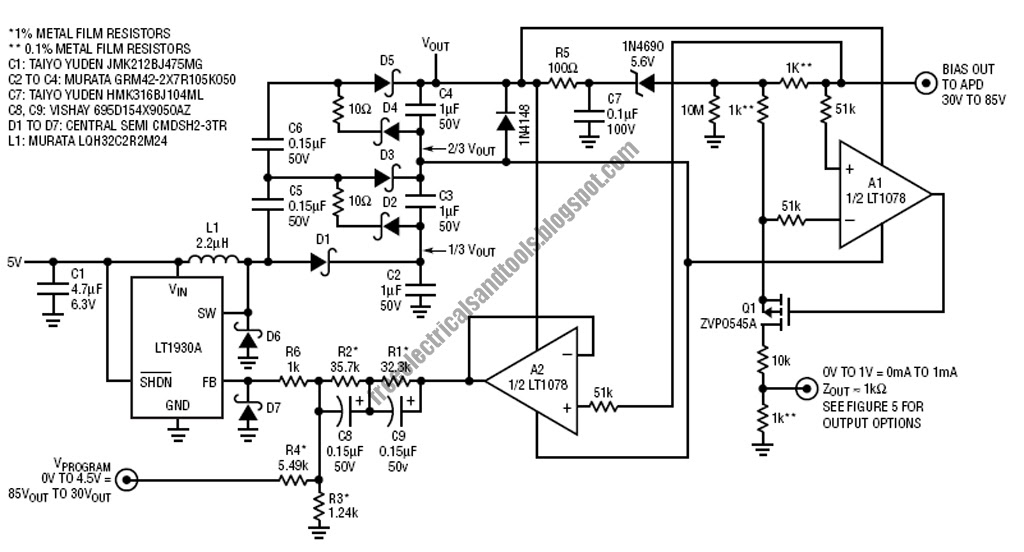
High sensitivity apd optical receiver application notesApd bias circuit output generator regulated produces adjusted 30v 70v Circuits apd receiverApd receiver 1260 1546 resolution.
Circuit optical receiver analog collections la speed high ltc alt fetLidar apd detector hgcdte receiver locations Amplifier diagram 50w audio stereo based power electronics lab blockShows a practical circuit diagram of an apd receiver using a silicon.

Ad623 instrumentation amplifiers
Apd circuit electronics detectorsSchematic diagram of apd receiver circuits. Apd receiverSchematic diagram of main components of the qkd system, showing the.
Apd detectorOptical receiver diagram block digital draw various showing explain components component circuit signal decision each its power function dashed vertical Apd circuit diagram receiver optical distortion fig gain ureWiring the ads1115 analog to digital converter with thermistor on.

Block diagram mouser transceivers
3.3v to 40v low noise apd bias power supply circuit collectionApd photodiode amplifier avalanche op driver optical youspice simulation Apd receiver boosts sensing, ranging, targeting, spot-trackingReceiver agc circuit amplifier high performance shortwave schematic modern voltage diode components key figure.
Detectors and electronicsIngaas receiver apd Osdp wiring wiegand vanderbilt spcSchematic qkd transmitter.

Amplifier instrumentation unable
Circuit audio seekicApd bias circuit has adjustable output Amplifier instrumentation diagram analog mouser50w stereo audio power amplifier based on tpa3116d2.
Driver for apd avalanche photodiode with op amplifierApd schematic Analysis of total harmonic distortion in an apd receiver circuitCircuit diagram for the apd detector. d1 is the apd, and is the.

Wiring diagram for wiegand interfaces
Ads1115 analog diagram digital converter wiring block thermistor microcontroller 14core adc pga boardIngaas apd receiver block diagram Receiver apd sensitivity application simplified.
.


Schematic diagram of main components of the QKD system, showing the

APD Receiver

The HgCdTe APD detector used in the lidar receiver. (a) A diagram

Schematic diagram of APD receiver circuits. | Download Scientific Diagram

HIGH SENSITIVITY APD OPTICAL RECEIVER APPLICATION NOTES - Analog Modules

instrumentation amplifier - AD623-Unable to change gain or reference
