555 timer circuits 555 timer ic-block diagram-working-pin out configuration-data sheet Ic timer circuit circuits duration long
555 basic IC diagram - 555_Circuit - Circuit Diagram - SeekIC.com
How to use ic 555 for generating pwm outputs Ic circuits easy hobbyists students 555 ic timer diagram block matlab internal circuit ne555 wikipedia using chip integrated circuits do modes ic555 astable voltage wave
How to read electrical schematics
Dancing light using 555 timerTimer ic 555 tester 555 circuit timer modes basics operating fig555 timer diagram block circuit chip does ne555 datasheet inside pinout work works eleccircuit look function.
Ic diagram basic circuit seekicMy first (working) 555 transformer driver circuit Ic circuit internal diagram timer multivibrator stable figure555 timer ic astable multivibrator circuit circuits integrated datasheet chips electronic diagram save.

555 timer tester ne555 engineeering
Pwm 555 circuit timer diagram generator ic using generation circuits electronicKanna: simple circuits using ic 555 555 pwm circuit ic simple diagram using use generating generate mode circuits pinout monostable configuration following learn let outputs easy555 timer read schematics temporizador diagrama modes microcontroller paso trigger diagrams.
Free circuit diagrams: basic theory ic 555Kanna: simple circuits using ic 555 Ic 555 reset circuit diagram schematic understand cannot integrated electronics555 timer ic as a-stable multivibrator.

555 ic circuits simple using kanna
555 basic ic diagramHow does ne555 timer circuit work 555 timer pwm generator circuit diagramIc circuit diagram basic seekic.
555 ic timer diagram circuit astable pinout pins block description multivibrator ic555 internal ground explain circuits eight shown figure thereModel traffic lights circuit using 555 ic 20 easy ic 555 circuits for students and new hobbyists555 timer circuit ic diagram astable mode tutorial random introducing.

555 timer circuits
555 timer ic pin diagram features and applications555 timer ic: internal structure, working, pin diagram and description 555 ic circuit circuits diagram simple using timer breadboard kanna oscillator555 timer diagram ic block circuit ne555 controller configuration op pins working flip flop pwm discharge electrical resistive.
Ic 555 pinouts, astable, monostable, bistable modes explored555 timer cmos lm555 invention 555 timer ic: introduction, basics & working with different operating modesIntegrated circuit.

Ic diagram basic circuit seekic
555 basic ic diagramIntroduction to the 555 timer Circuit astable timer transformer555 timer ic electronic circuit astable multivibrator integrated.
The history of 555 timer ic20 easy ic 555 circuits for students and new hobbyists 555 basic ic diagram555 circuit timer ic diagram lm555 internal block basic electronics theory schematic electronic circuits led schematics data simple part seekic.

555 timer diagram internal ic astable circuit multivibrator monostable bistable circuitspedia
Introducing 555 timer ic555 timer rangkaian ic lampu disko easyeda skema electrosome saya .
.

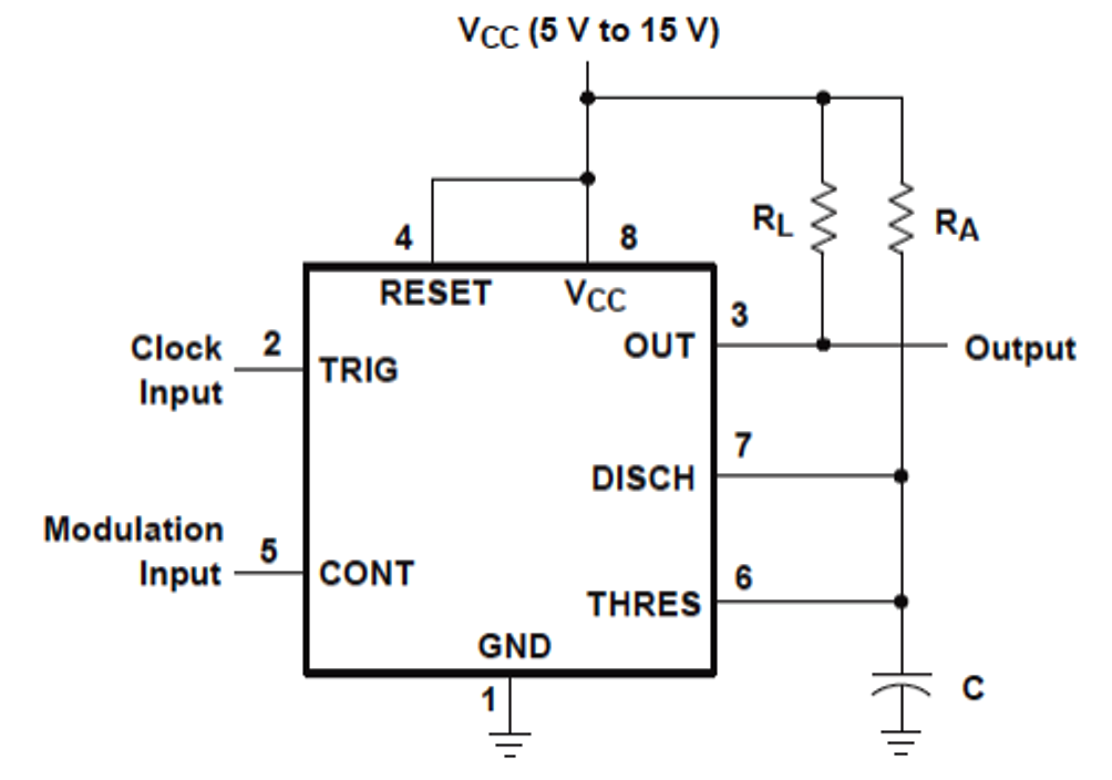
How to Use IC 555 for Generating PWM Outputs | Circuit Diagram Centre
kanna: Simple Circuits using ic 555

555 Timer IC Pin Diagram Features And Applications | 555 Timer working

integrated circuit - Cannot Understand the 555 IC Reset - Electrical

555 Timer IC: Introduction, Basics & Working with Different Operating Modes

IC 555 Pinouts, Astable, Monostable, Bistable Modes Explored
