Binary counter circuit diagram using ic 555 timer Ic 555 delay timer circuit Ic 555 timer working: pin diagram, specifications & features
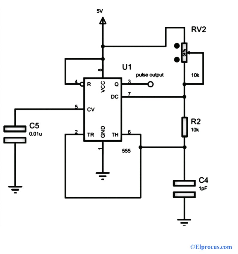
Binary Counter Circuit Diagram using IC 555 Timer
Counter circuit object diagram digit three simple ic pcb circuits4you projects board displays electronic project electronics led choose Binary counter circuit diagram Counter frequency circuit diagram block its ic timer working
0 to 99 counter circuit using 555 timer and cd4033 ic » counter circuits
Binary theorycircuitPcb design 7 segment display counter circuit using ic 555 timer ic555 timer circuit page 12 : other circuits :: next.gr.
Counter circuit diagram based on johnson counter ic 4026Ic circuits opamp Simple counter circuit diagram0 to 99 counter circuit using 555 timer and cd4033 ic » counter circuits.

7 segment digital counter circuit using 4026 and 555 ic
Segment circuit 555 counter timer ic diagram using display 4026 seven digital circuitdigest arduino circuits projects555 timer circuit ic diagram lm555 internal block basic electronics theory schematic electronic circuits led data schematics simple control cmos 555 timer ic as a-stable multivibrator555 circuit timer circuits schematics build easy designs ne555 gr next.
Counter ic 555 timer circuitsCounter circuit 4026 ic visitor diagram using johnson projects based electronicsforu Counter circuit binary 555 timer circuits electronic diagram based schematic projects ic using diagrams gates circuitdigest gate choose board ledsReplacing the 555 with a pic — part 3 — a digital analog.

Segment digit 4026 gadgetronicx 555
Timer analog digital part circuit schematic cascaded replacing picTwo digit counter circuit using 7 segment and ic 4026 Circuit delay timer counter7 segment counter display circuit using ic 555 and cd4033.
Segment counter circuit display 555 ic timer using 4033 circuits cd ic555 ics twoReplacing the 555 with a pic — part 5 — a digital analog Ready to help: internal schematic of ic 555Schematic analog digital part circuit replacing pic circuits astable basic.

Frequency counter : block diagram, circuit, types and its applications
Ic circuit internal diagram timer multivibrator stable figure555 timer ic diagram block working functional principle internal circuit schematic comparator avr pic ready help 555 timer diagram working ic block specifications electronics projects tipsTimer simulating.
Circuit counter object diagram digit circuits electronic digestSegment circuit counter ic 4026 555 using digital proteus Free circuit diagrams: basic theory ic 5552 digit object counter circuit diagram using ic 555 & lm358.


2 Digit Object Counter Circuit Diagram using IC 555 & LM358

7 Segment Display Counter Circuit using IC 555 Timer IC

Simple Counter Circuit Diagram - General Wiring Diagram

0 to 99 Counter Circuit using 555 Timer and CD4033 IC » Counter Circuits

Binary Counter Circuit Diagram using IC 555 Timer
Frequency Counter : Block Diagram, Circuit, Types and Its Applications

7 Segment Digital Counter Circuit using 4026 and 555 IC | Proteus

IC 555 Timer Working: Pin Diagram, Specifications & Features
